
This article introduces the latest work from Professor Luyu Lu’s team at Chongqing University, recently published in Fuel. The study utilised a custom-designed load-injection NMR system to monitor the dynamic evolution of coal pore-fracture structures during hydraulic fracturing under simulated in-situ conditions, providing valuable guidance for hydraulic fracturing engineering.
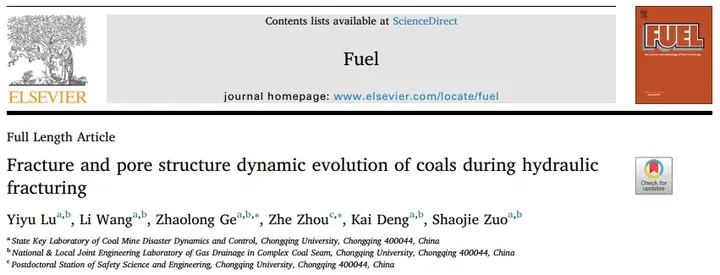
Hydraulic fracturing is an effective method to enhance coalbed methane production. To better understand the evolution of macroscopic fractures and pore-fracture structures during hydraulic fracturing, a series of in-situ compression experiments under continuous water injection were conducted, with dynamic monitoring using NMR. Changes in porosity and different pore components during the fracturing process were analysed in relation to confining and injection pressures. This research offers valuable insights for permeability calculations, CBM productivity prediction, and optimisation of hydraulic fracturing technology. Introduction: Coalbed methane is an unconventional gas resource, and its extraction is limited by low permeability. Hydraulic fracturing is widely applied, injecting water continuously into the coal to create primary and secondary fractures that serve as migration pathways for gas, thus reducing extraction difficulty, as illustrated in Figure 1. Understanding the evolution of coal pore-fracture structures during hydraulic fracturing is essential.
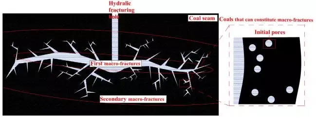
Figure 1 Formation of macroscopic fractures in the hydraulic fracturing zone
Hydraulic fracturing involves the continuous injection of fluid into coal, making the evolution of pore-fracture structures a dynamic process. Current studies in this area are limited. This work provides real-time, precise testing of coal pore-fracture structure evolution under continuous fluid injection.
Load-injection NMR is a crucial technique for studying pore-fracture evolution under simulated in-situ stress and continuous injection conditions. Traditional methods, including gas adsorption, mercury intrusion, small-angle X-ray scattering, and scanning electron microscopy, cannot apply pressure to samples. CT and micro-CT have limited resolution. A comparison of these methods is shown in Figure 2. NMR enables simple, real-time analysis of pore size distribution. However, NMR alone cannot fully observe pore-fracture evolution under combined stress and injection conditions, which led to the development of the load-injection NMR system shown in Figure 3. Coal cores were 25.4 mm in diameter and 60 mm in length. The system applies confining pressure radially using fluorinated oil, with a maximum of 25 MPa, up to 150℃, while liquids or gases are injected axially into the core.

Figure 2 Comparison of different testing methods
Hydraulic fracturing can be divided into four stages based on injection pressure: coal fracturing, pressure maintenance, pressure unloading and extraction, and completion. During the coal fracturing stage, injection pressure rises or is maintained; in the pressure maintenance stage, fluid diffuses at constant injection pressure; in the pressure unloading-extraction stage, fluid leaves the coal, reducing pressure; in the completion stage, remaining fluid exits without further injection. Injection pressure, pore pressure, effective stress, and deformation all influence pore-fracture structures, with injection pressure and confining pressure being the main variables. In this study, we examined coal pore-fracture evolution under varying injection and confining pressures using three loading modes: fixed confining and injection pressures, fixed confining with variable injection pressure, and fixed injection with variable confining pressure.
Coal cores were placed in the load-injection system, with injection pressure applied via distilled water, and NMR scanning monitored pore-fracture evolution. The NMR system, MacroMR 12-150H-I, was manufactured by Newmai, Suzhou. After 120 minutes of stable confining or injection pressure, T₂ curves remained nearly unchanged. Experimental details are listed in Table 1.

Figure 3 Load-injection NMR system
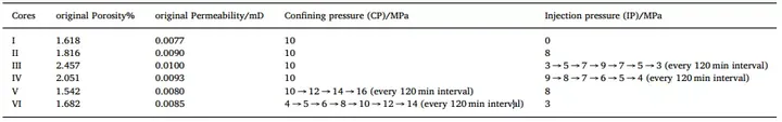
Table 1 Coal core loading modes
To validate load-injection NMR results, mercury intrusion and gas adsorption tests were performed. Each T₂ value corresponds to a specific pore size, so T₂ spectra reflect the pore-fracture distribution. Pores were classified as micropores and transition pores (<2.5 ms), mesopores (2.5–100 ms), and macropores and fractures (>100 ms). Relationships between T₂ values and pore structures under different loading conditions are given by the following formulas:
Where T₂ is the transverse relaxation time (ms); S is the pore surface area (nm²); V is the pore volume (nm³); ρ₂ is the transverse surface relaxation coefficient (nm/ms); r is the pore radius; Fₛ is the geometric shape factor.
Changes in T₂ curves indicate the evolution of pore-fracture structures under continuous fluid injection. T₂ spectra exhibit three continuous peaks. As shown in Figure 4, at 10 MPa confining pressure and zero injection pressure, P₂ and P₃ peaks are negligible, while P₁ at time zero is higher than other times. When injection pressure is applied, P₂ and P₃ peaks become significant, and all peaks are lower than other times, indicating increased porosity and continuous pore-fracture evolution. Peaks P₁, P₂, and P₃ respond to confining and injection pressures, highlighting the strong influence of these factors on coal pore-fracture structures.

Figure 4 T₂ curve changes under different loading modes
Effect of confining and injection pressures on porosity: When confining pressure is fixed and injection pressure varies, mesopores, macropores, and fractures remain limited. Cumulative peak areas for T₂ >2.5 ms and <2.5 ms are shown in Figure 5. Three cumulative curves are displayed: total porosity (Total-P), micropores-transition pores (MP-TP), and mesopores (MEP) combined with macropores-fractures (MP-F), calculated as follows:

Total porosity increases significantly during injection. With fixed confining pressure, it does not decrease with lower injection pressure; with fixed confining and injection pressures, it first decreases then increases. As Figure 5a shows, at 10 MPa confining pressure and zero injection pressure, total porosity decreased by 83.9% in the first 60 minutes, then increased by 85.1% between 840–960 minutes, forming a U-shaped trend. Figure 5b shows that at 10 MPa confining and 8 MPa injection pressures, total porosity increased by 84% in the first 120 minutes, then dropped by 32% at 480–600 minutes, and rose by 30.6% at 1320–1620 minutes, also U-shaped. Figure 5c shows an initial 51.6% increase in total porosity during the first 15 minutes; when injection pressure decreased from 7 to 3 MPa, mesopores and macropores-fractures decreased while micropores-transition pores increased. Variance of total porosity remained 0.01–0.015, essentially unchanged (Figure 5d).
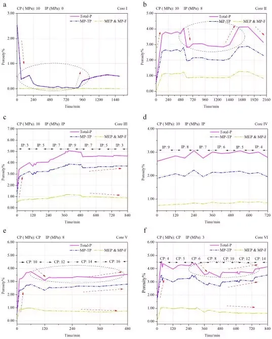
Figure 5 Micropores-transition pores, mesopores, macropores and fractures under varying injection and confining pressures
With constant injection pressure and varying confining pressure, total porosity increases during injection. Under constant or rising confining pressure, total porosity first decreases then increases. Mesopores and macropores-fractures decrease, while micropores-transition pores increase. Figure 5e shows a 79.9% increase in total porosity during the first 10 minutes; when confining pressure rose from 10 to 12 MPa, total porosity decreased by 17.5%. Overall, total porosity and micropores-transition pores rise with confining pressure, while mesopores and macropores-fractures decline. Figure 5f shows total porosity increased by 62.7% in the first 30 minutes, then decreased by 17% as confining pressure increased from 6 to 8 MPa.
Pore-fracture structure testing without confining and injection pressures
NMR, gas adsorption, and mercury intrusion tests were performed after releasing confining and injection pressures for the three loading modes. Core I was from fixed confining and injection pressures, Core III from fixed confining with variable injection pressure, and Core V from fixed injection with variable confining pressure. Gas adsorption measured pore sizes 0.35–500 nm; mercury intrusion measured >30 nm, combining the methods for a broader pore size distribution.

Figure 6 T₂ spectra and pore-fracture distribution combining mercury intrusion and gas adsorption under zero confining and axial pressures
Under zero confining and injection pressures, the main pores are micropores and transition pores. In Core I, NMR indicated micropores-transition pores accounted for 96.5% of total porosity, mesopores 3.5%; gas adsorption-mercury intrusion measured 94.9%, 2.2%, and 2.6%, respectively. Core III showed 81.8%, 8.3%, and 9.9% by NMR, and 84.6%, 5.5%, and 9.3% by adsorption-mercury intrusion. Core V showed 91.4%, 6.6%, and 2.0% by NMR, and 91.1%, 5.7%, and 2.5% by adsorption-mercury intrusion. Differences between NMR and combined methods were 0.3–2.8%, demonstrating excellent agreement and reliability of NMR for pore-fracture characterisation.
Effect of confining and injection pressures on pore-fracture structures

Figure 7 Evolution of pore-fracture structures by pore size and type
Pore-fracture evolution varies by pore size and type. Under constant or increasing confining pressure, total porosity first decreases then increases. When injection pressure is reduced or confining pressure increased, mesopores and macropores-fractures decline while micropores-transition pores rise. Figure 7a shows Core I T₂ spectra decreasing over 0–240 minutes with decreasing total porosity (compression), then increasing during 840–1140 minutes (Figure 7b).
During initial injection, Core II T₂ spectra exceeded initial values, indicating continuous fluid penetration. Between 10–120 minutes, porosity channels formed, facilitating fluid flow. Peaks 2 and 3 decrease with lower injection or higher confining pressures, while peak 1 increases, indicating reduction in meso/macropores-fractures and increase in micropores-transition pores.
Application of dynamic pore-fracture evolution in hydraulic fracturing
This study investigated pore-fracture evolution during continuous fluid injection under varying confining pressures in hydraulic fracturing:
(1) Fracture initiation stage: Injection pressure applied, fluid changes induced, porosity increases significantly in the injection zone, forming pore channels.
(2) Pressure maintenance stage: Injection pressure constant, fluid changes continue, certain pore channels form, highlighting the importance of pressure-holding.
(3) Pressure unloading stage: Injection pressure decreases, structural reconfiguration occurs, porosity decreases.
(4) Completion stage: Fluid exits the coal, pore-fractures gradually close under in-situ stress; porosity may temporarily rise.
Conclusion: Using the loading-injection NMR system, dynamic pore-fracture evolution during fluid injection and confining pressure variation was monitored in real-time.
Key findings: During initial injection, total porosity increased, forming pore channels. With constant confining pressure and reduced injection pressure, or constant injection pressure and increased confining pressure, mesopores, macropores, and fractures break down into micropores and transition pores, decreasing meso/macro-fracture numbers and increasing micro/transition pore numbers. Under constant injection with rising confining pressure or constant injection and confining pressures, total porosity first decreases then increases; fluid injection or pore water breaks pore walls, generating new pores. Changes in effective stress and pore pressure under confining pressure and continuous fluid injection lead to fracture, closure, and continuous reorganisation of pore-fracture structures.
 Scan QR Code
 Scan QR Code
Phone: 400-060-3233
After-sales: 400-060-3233


Back to Top